Where did you get this? I’m assuming that’s how

you turn your lights on/off
How did you run the 4 gauge from the front battery to the bed battery bank?
I’m running Hardkorr lights and that is the switch that came with the lights. It’s nice as it gives me dimmer control and 3 different color modes (amber, white, and warm white (a mix of the amber and white leds).
I have actually redesigned the electrical system but the cable routing is the same regardless. I have a secondary battery mounted in the engine bay on the passenger side fender (Off Grid Engineering mount). It would be the same if you were running the cables from the OEM location, you’d just have to cross over. I dropped the cable down to the frame, along the firewall, by the body mount, and followed the factory cabling back to the rear cab mount. Be sure to insulate your cables to protect them from the heat of the catalytic converters and the muffler. To get it into the bed I used to run it through the gap between the bed header rail and the side rail and plugged it with butyl rubber. Now I have a 2.5" hole in the front, lower corner of the bed. I had SendCutSend manufacture two aluminum plates that go around the hole and sandwich a piece of rubber against either side of the bed. It’s tucked up right behind the rear fender liner by the rear cab mount and has been pretty dustproof thus far.
I’m sorry I don’t have any good pictures of the grommet but my truck is 2000 miles away right now.
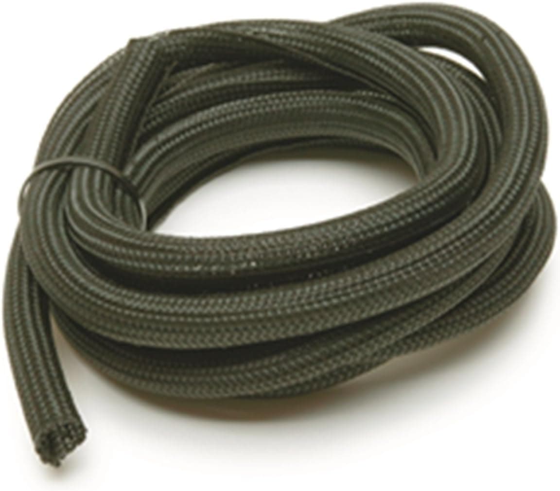
Here’s an image of the bracket I used to make a grommet sandwich with the bed, and what kinds of sleeving I used on the cables. The whole length was protected with a braided sleeving, and whatever was near the cats were additionally wrapped in velcro on aluminized insulation.

Now why I redesigned the system. My group 35 deep-cycle battery just wasn’t cutting it to run the fridge, even up here in the PNW. I’d often come back to the fridge off after about 18 hours.
I ripped out the old 4-gauge cabling (also way thicker than needed) and ran a 6 or 8-gauge cable from the positive terminal of each battery to the back (fused at 30 amps which is super conservative, but all I need). I then ran those into different Anderson connectors and grounded them to the frame (running additional grounding cables at the front, from the frame to the batteries).
The positive from the primary battery (and by extension the alternator) is running into a Victron 20 amp, 12 to 24-volt step-up converter that is switched on or off with the ignition (Victron Energy ORI122420020 Orion 12/24-20 Step-Up DC/DC Voltage Converter). That powers an Ecoflow Delta 2 through the solar charge port (could power any solar generator with the right connector. Goal Zero, Jackery, etc.). This allows me to charge at 400+ watts whenever the engine is running. Tinkerer’s Adventure has a good video on how he uses a similar setup (https://youtu.be/s_-9vj-hF1M?si=jsjUpAYs94zSG9QV).
The secondary battery powers a Blue Sea fuse block which runs some simple 12-volt outlets and the lights in the canopy. I decided to do this because I don’t always have the Ecoflow back there and I wanted some basic electrical stuff to still work in those situations.
Sounds complicated, but it is quite simple to use. It’s also entirely “connecterized” in the right spots so the camper can still lift off easily. That is my design philosophy with any mod on the truck, it must be easily removable without cutting too many zip-ties or having to redo wiring.
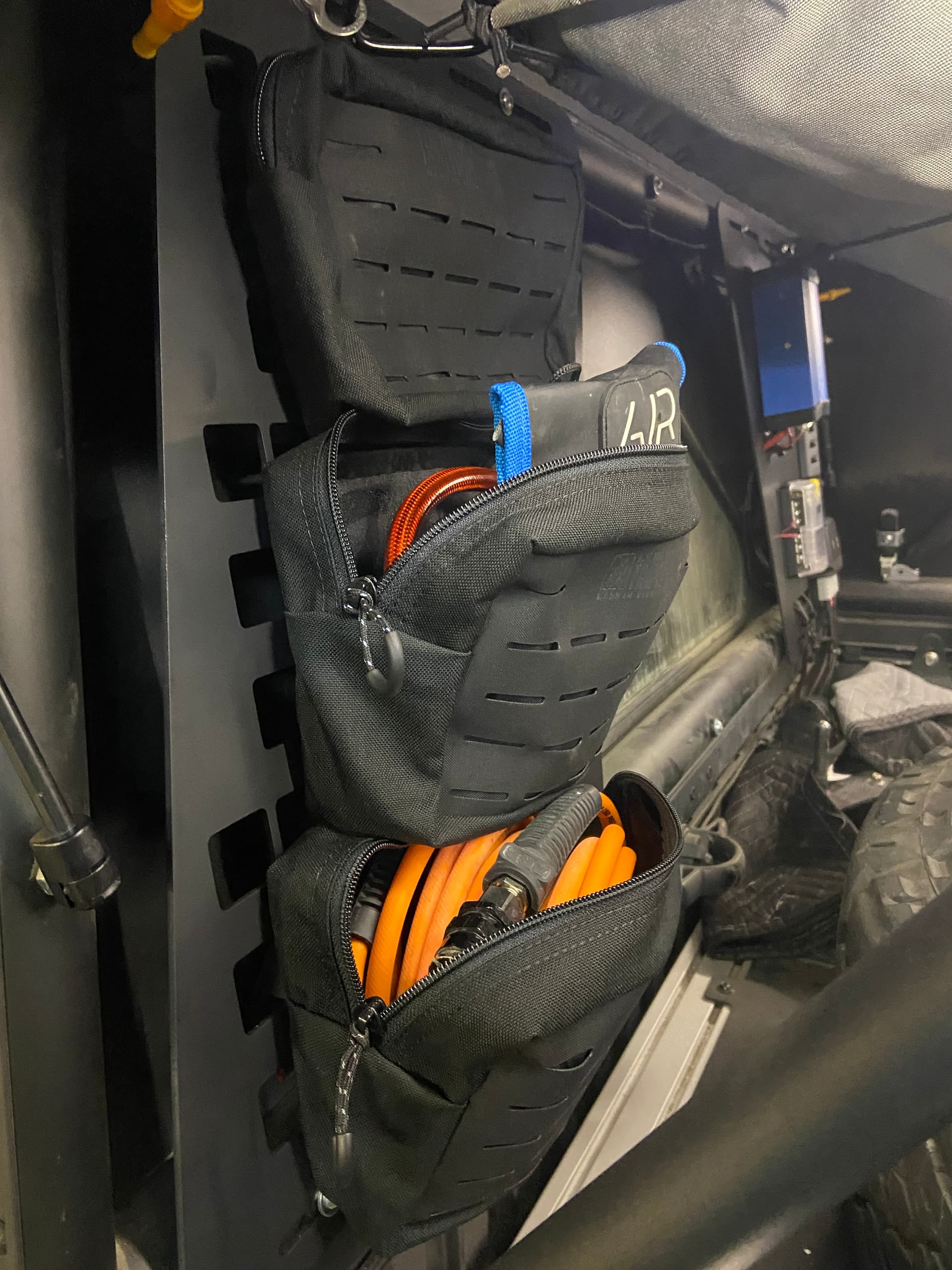
I don’t have great photos but I’ll post what I’ve got. Oh and a pic of my MOLLE panel design.