I’ve been working on upgrading my 100W system from last year to a 200W system so I can plug in a small freezer, lights and a charging panel but I am feeling a little.. stuck haha.
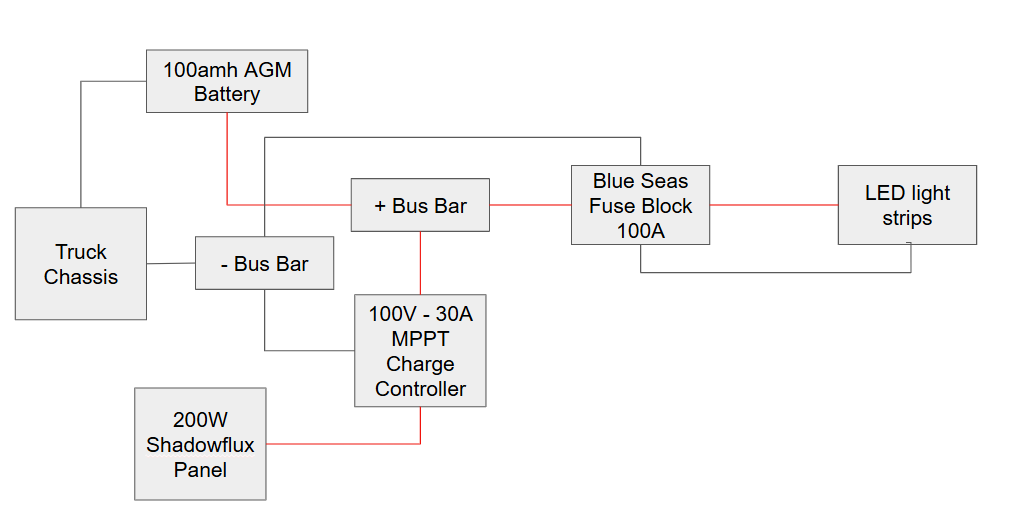
I’m receiving charge from the panel to the charge controller (its in Float mode). The battery is fully charged and when I connect hot and ground wires from the LED strips directly to the battery they work no problem. But somehow when I wire it through a bus-bar and fuse block nothing works. There is no blown fuse in the fuse block and the bus-bar is brand new.
Why do you have a secondary positive buss bar? If you are running a blade fuse block, run all the accessories to that. Run the charge controller to the battery. Furthermore, are you running any other accessories off the fuse block? If so, do they work?
The first diagram doesn’t show a ground from the light strips. Is this just a mistake?
Also, I would run a two pole solar disconnect switch. That way, when you’re working on stuff, you can completely kill power coming from the solar panel.
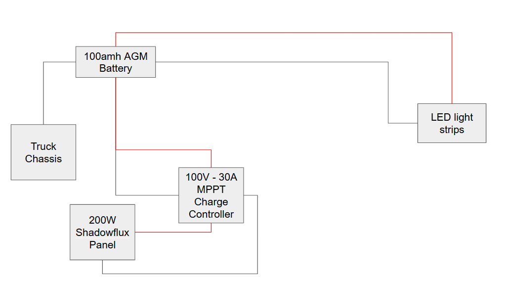
+1 almost certainly a floating ground. You still need a dedicated negative run from the LED strips back to your fuse block or directly to battery terminal.
I only have 1 positive bus bar and 1 neg bus bar, which one were you referring to? And yes, there is a ground from the led strip going back to the ground on the fuse block (i fixed the diagram).
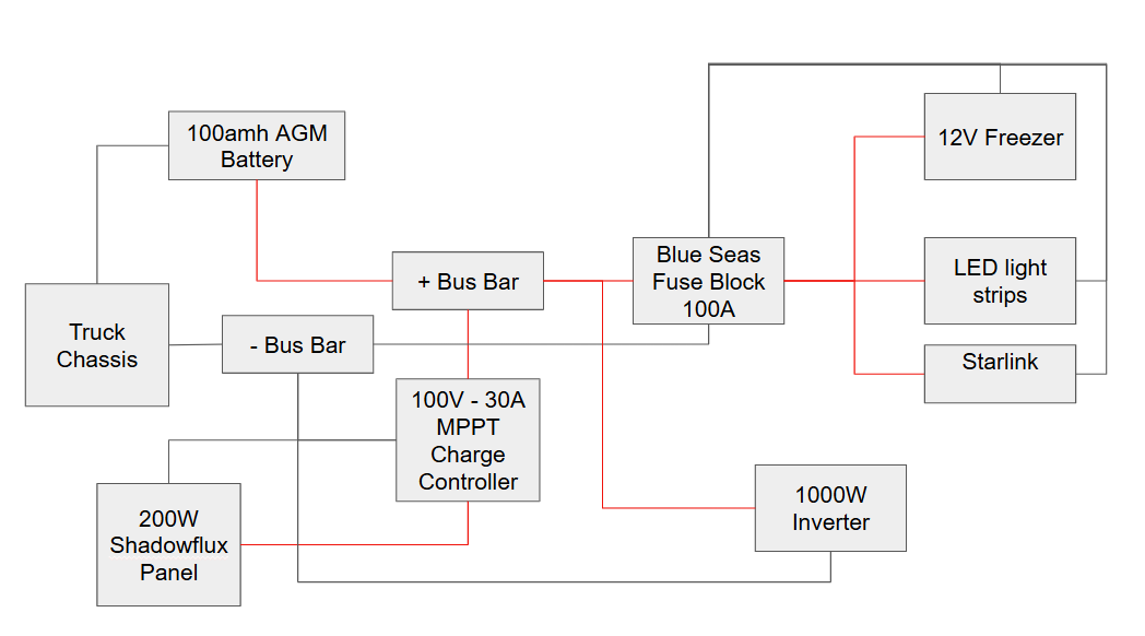
All my accessories will run to the fuse block and yes, there is a small 12V fridge, star link and a phone charger. These also don’t work. I am using a busbar system because I also want to add an inverter.
Please do, and add pics if you can. I’d love to see how you’re organizing these components. I’ve had my molle panel sitting on my office floor with all of my individual pieces and can’t decide how to best place them.